The schematics for Shadowfax's various subsystems are shown below.
Beacon Sensor
The beacon sensor was used to locate the other robot. Shadowfax carries three robot beacon sensors, one located at the front, one in the middle, and one at the rear. All three sensors passed the signal through a transresistive circuit, as well as a high pass filter, a unity gain buffer (centered and railed at ground to chop off half of the signal and give us noticeable differences), and a low pass filter to cut the signal to a simple analog input. Additionally, before the high pass filter, the front and middle signals were passed through a fourth order Chebyshev 3dB filter, an active low pass filter, as there was the possibility that these two sensors could be pointing at both the robot beacon and the goal beacon. This filter allowed us to effectively eliminate any interference from the goal beacon (we got about a 30 mV signal compared to a nearly 900 mV signal from the other robot). We opted for this approach to maintain an analog signal, therefore allowing us to alter the distance we react to an opponent in code once we had judged the speed other robots were moving with. The reaction of each sensor at various distances was recorded for this use as shown below.
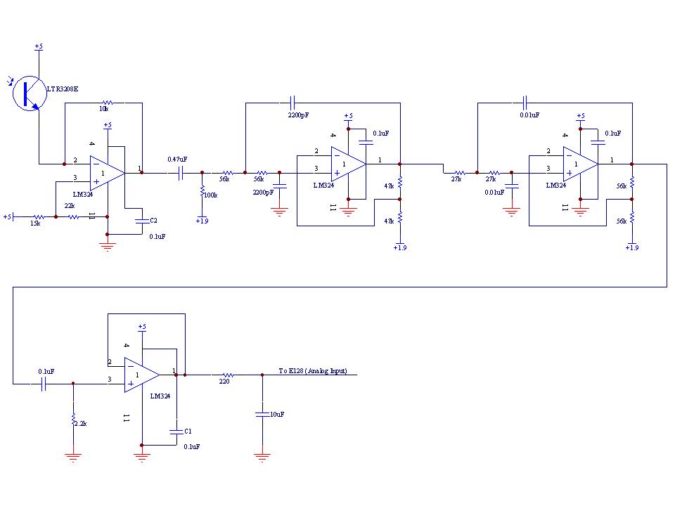
Front and Mid Robot Beacon Sensor Schematic
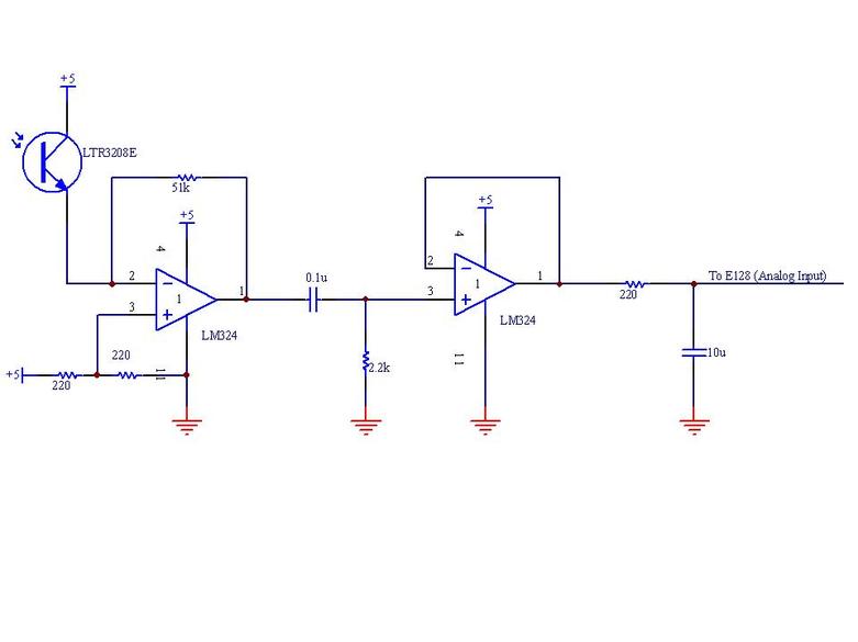
Rear Robot Beacon Sensor Schematic


These figures show the results of testing the sensors reaction to an opposing head at various distances. They were used to determine at what values we wanted the lance to be deployed at, for example if we wanted to deploy the lance when the opposing robot was approximately 24" away, we could set the trigger point to be a read of approximately 60 on the analog input pin tied to the front beacon.
Coin Sensor
An IR LED and an IR Phototransistor were used in conjunction to count the number of balls collected from the reload station.
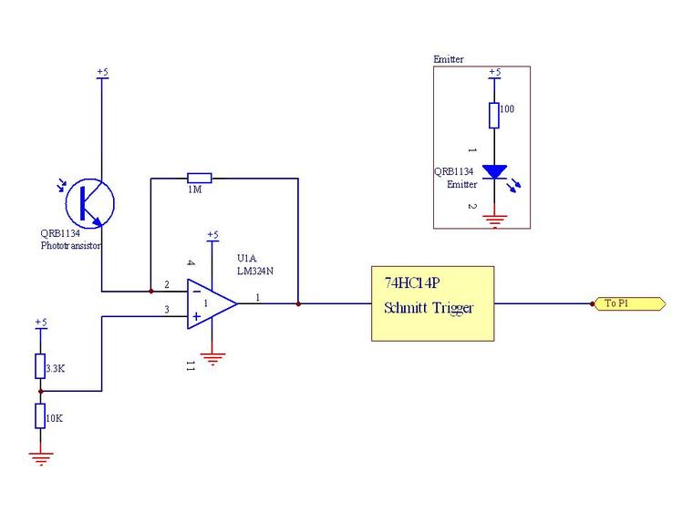
Coin Sensor Schematic
Goal Beacon Sensor
This beacon sensor was used to detect the goal. This sensor was passed through a nearly identical filter to the rear robot beacon sensor, only adjusted to react well to 2083 Hz instead of 1250 Hz.
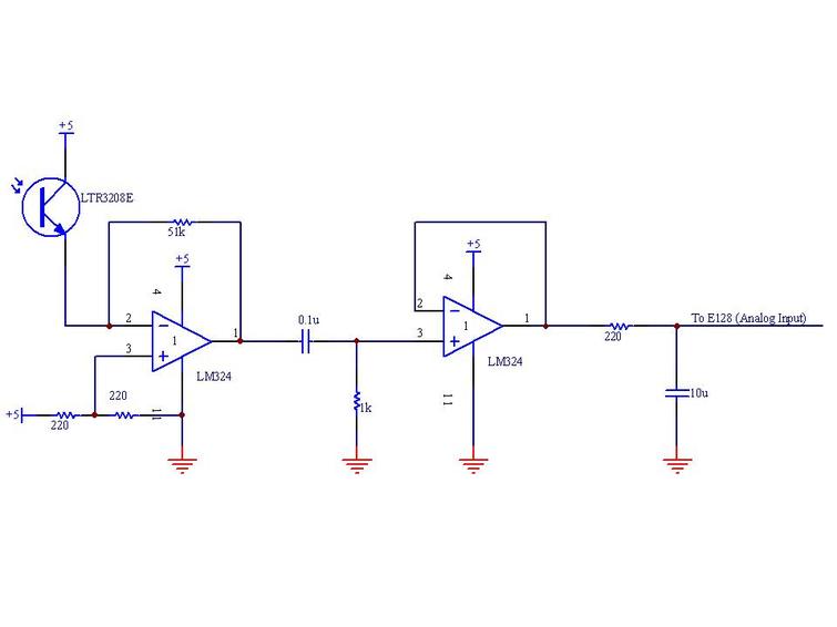
Goal Beacon Sensor Schematic
IR Blaster
Shadowfax communicated with the reload station via pulses emitted by IR LEDs in series. These IR LEDs were located at the back of the robot, with one red LED in series to show when the pulses were being sent.
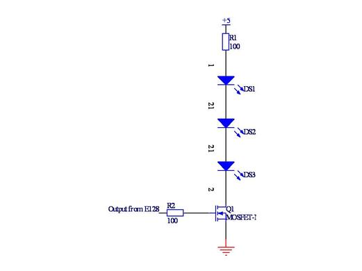
IR Blaster Schematic
Limit Switches
We used limit switches on the front and back of the robot to determine when we hit the back wall of the playing field. Limit switches were also used along the side of the robot to maintain alignment along the dividing wall of the field.
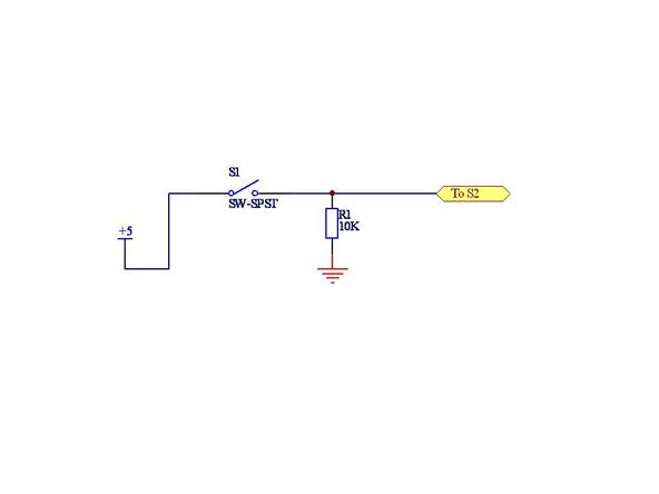
Schematic for One Limit Switch Circuit
Drive Motors
We used the class supplied motors to drive Shadowfax (as required by the rules). Motor control was done with PWM through an LMD182000 controller.
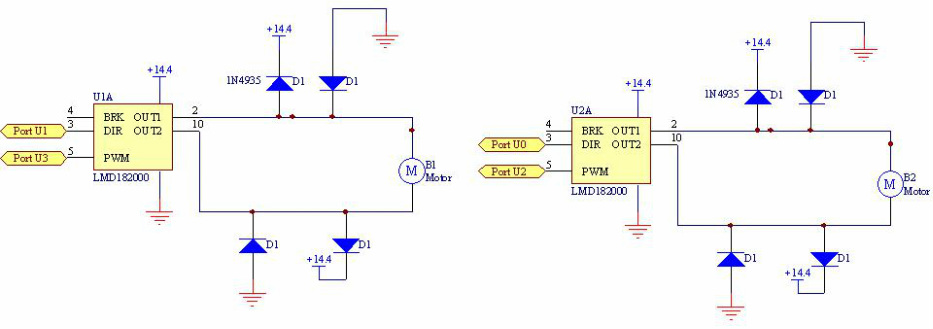
Schematic for Drive Motors
Servos
Shadowfax has the capability to use four servo motors: two high-torque servos to move the lance and two micro-servos to control ball movement. Both lance servos were implemented, while we determined only one servo was needed to stop/start the release of balls to the shooter motors.
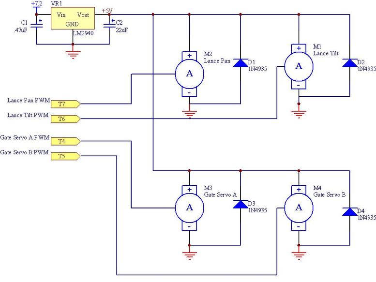
Schematics for all Four Servo Motors Implemented
Shooters
The shooter motors were set up similar to a baseball-pitching machine and fed balls. They were controlled through an IRLZ34N power MOSFET and using a PWM signal from the E128
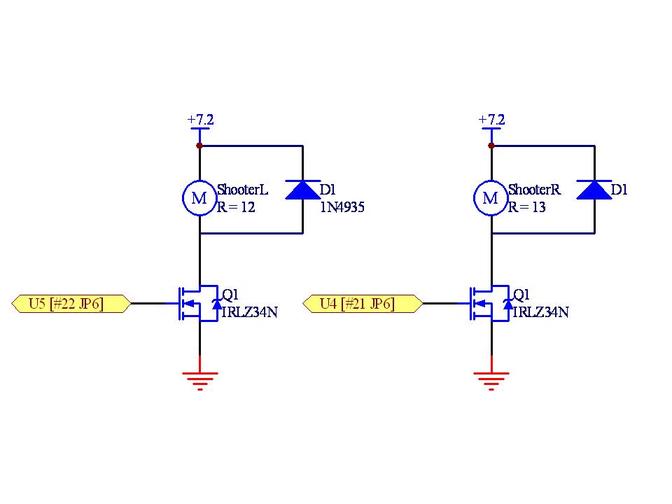
Schematics for the Motors Used to Shoot the Foam Balls
E128 Connections
. | ||||||||||||||
. | JP6 | Subsystems | ||||||||||||
. | 1 | 24 | Drive | |||||||||||
. | 2 | U7 | GND | 23 | Shooter | |||||||||
. | 3 | U6 | U5 | 22 | L Shooter PWM | (PWM) | Lance | |||||||
. | (Dig OUT) | Goal Detect LED | 4 | T0 | U4 | 21 | R Shooter PWM | (PWM) | Display | |||||
. | (Dig OUT) | Reloader IR LEDs | 5 | T1 | U3 | 20 | L Motor PWM | (Dig OUT) | Miscellaneous | |||||
. | (Dig IN) | Right Shooter Encoder | 6 | T2 | U2 | 19 | R Motor PWM | (PWM) | ||||||
. | (Dig IN) | Left Shooter Encoder | 7 | T3 | U1 | 18 | L Motor Dir | (Dig OUT) | ||||||
. | (Timer) | Gate Servo A | 8 | T4 | U0 | 17 | R Motor Dir | (PWM) | ||||||
. | (Timer) | Gate Servo B | 9 | T5 | E7 | 16 | Knight Color Indicator | (Dig IN) | Timers | Purpose | Module | Uses physical pin? | ||
. | (Timer) | Lance Tilt Servo | 10 | T6 | T7 | 15 | Lance Pan Servo | (Timer) | T0 CH4 | |||||
. | 11 | E0 | E1 | 14 | T0 CH5 | IR LEDs | ReloadSM.c | yup | ||||||
. | 12 | 13 | T0 CH6 | R Shooter Encoder | Motor.c | Yes | ||||||||
. | Ribbon Cable ---> | T0 CH7 | L Shooter Encoder | Motor.c | Yes | |||||||||
. | T1 CH4 | Gate servo A | KentuckyServo.c | Yes | ||||||||||
. | JP5 | T1 CH5 | Gate servo B | KentuckyServo.c | Yes | |||||||||
. | 1 | GND | GND | 20 | T1 CH6 | Lance tilt servo | KentuckyServo.c | Yes | ||||||
. | (Dig IN) | Front Bumper Limit | 2 | S2 | P5 | 19 | Visual Indicator Round 3 | (Dig OUT) | T1 CH7 | lance pan servo | KentuckyServo.c | Yes | ||
. | (Dig IN) | Rear Bumper Limit | 3 | S3 | P4 | 18 | Visual Indicator Round 2 | (Dig OUT) | T2 CH4 | Control loop timer | Motor.c | No | ||
. | (Dig IN) | Front Drive Limit | 4 | P2 | P3 | 17 | Visual Indicator Round 1 | (Dig OUT) | T2 CH5 | No | ||||
. | (Dig IN) | Rear Drive Limit | 5 | P0 | P1 | 16 | Ball Hopper Coin Sensor A | (Dig IN) | T2 CH6 | No | ||||
. | (Dig IN) | Ball Hopper Coin Sensor B | 6 | AD0 | AD4 | 15 | Robot Sense BACK | (Analog) | T2 CH7 | No | ||||
. | (Dig OUT) | Reload Indicate LED | 7 | AD1 | AD5 | 14 | Front Tape Sensor | (Analog) | ||||||
. | (Analog) | Robot Sense FWD | 8 | AD2 | AD6 | 13 | Rear Tape Sensor | (Analog) | ||||||
. | (Analog) | Robot Sense SIDE | 9 | AD3 | AD7 | 12 | Goal Beacon Sense | (Analog) | ||||||
. | 10 | GND | GND | 11 | ||||||||||
. | <--- Ribbon cable | |||||||||||||
. | ||||||||||||||
. | ||||||||||||||
. | ||||||||||||||
. | ||||||||||||||
. | ||||||||||||||
. | ||||||||||||||
. | L | |||||||||||||
. | ||||||||||||||
